Frequently Asked Questions About Ball Bearing and Ball Bearing Usage
You can find frequently asked questions about ball bearings and usage of ball bearings and the related explanations, which were prepared by our experienced engineer crew, via this page.
After choosing the type of the ball bearing, its’ size is determined according to either its static load bearing capacity or dynamic load bearing capacity. If the ball bearings do not work for a long time or if they turn relatively slowly, you may calculate them according to static load bearing capacity, if they work for long time periods, it can be chosen according to dynamic load bearing capacity.
Determining the size according to static load bearing capacity: Static load bearing capacity calculation is made on the basis of certain permanent deformation of the bearing under constant load. In order to compare the loads on the bearing with the load carrying capacity given int the catalog, we need to reduce the effect of the radial and axial loads to a single equivalent load.
Equivalent load for static load carrying capacity (Po):
Po=Xo.Fr + Yo. Fa
Here,
Fr: Radial load on the bearing,
Fa: Axial load on the bearing,
Xo: Static radial factor,
Yo: Static axial factor,
(Xo and Yo values take different values according to the Fa/Fr ratio. For this reason, it is necessary to find the Fa/Fr ratio first and then select the Xo and Yo coefficient according to this ratio.)
After determining Fr, Fa, Xo and Yo, the static equivalent charge, Po, can be found. When we compare this value with the static load number Co in the catalog, we find how safe the bearing is: Co/Po ratio gives us the factor of safety at that load.
Determining the size according to the dynamic load carrying capacity: Dynamic load carrying capacity is based on life calculation (not permanent deformation).
Equivalent load (P) for dynamic load carrying capacity:
P=XFr + Yfa
Here,
Fr: Radial load on the bearing,
Fa: Axial load on the bearing,
X: radial factor,
Y: axial factor,
Similar to the calculation of the static load carrying capacity, the X and Y values take different values according to the Fa/Fr ratio. For this reason, it is necessary to find the Fa/Fr ratio first and then choose the X and Y coefficients according to this ratio. After determining Fr, Fa, X and Y, the dynamic equivalent load, P, can be found. Since dynamic loads are based on life calculation, the C value in the catalog indicates the load (90 out of 100 bearings) can carry for one million cycles of life.
The number of millions of round the bearing will make at P equivalent load is found by the formula:
For ball bearings, L=(C/P)^3 – For roller bearings L=(C/P)^(10/3)
Here,
L: Life in millions of rounds.
C: Number of dynamic loads (given in the catalogues),
P: (Calculated) equivalent dynamic load,
The life in operating hours can be calculated using the round per minute (n) of the shaft.
Life in operating hours=L*10^6/(60*n)
Unfortunately, user errors are at the top of the factors affecting the bearing life. Wrong bearing selection, mounting error, incomplete and improper lubrication are the main causes of user errors. It is important to get help from your supplier about the selection and use of the bearing according to the application area.
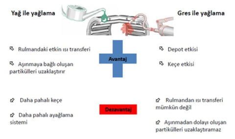
Lubrication performs the following tasks inside a bearing:
- Lubrication of sliding surfaces (reduction of friction between the balls or rollers and the cage)
- Lubrication of rolling surfaces (bearings with balls or rollers)
- Protection against corrosion in the bearing
- Preventing external factors (dust, moisture, etc.) from entering the bearing
- Aid in heat transfer (heat flow to the outer casing of the bearing)
- If the bearings came to you unlubricated, they must be lubricated with grease by you.
General Recommendations:
- n x dm > 100.000 [min-1 x mm],
- To fill 20% to 25% of the gap,
- n x dm < 50.000 [min-1 x mm],
- To fill 100% of the entire space,
It should be lubricated so that 50% of the space between the housing in which the bearing is placed and the right and left of the bearing is filled.
The main difference between capped bearings and uncapped bearings is that the capped version protects the bearing from unwanted foreign particles. With the capped version, keeping the grease inside the bearing can be considered as another advantage. However, some versions of covered bearings that provide contact sealing have a disadvantage that they operate at lower speeds than the versions without cover due to friction.
Covered bearings are basically divided into two according to the application;
- Contact sealing (bearings with plastic covers): full protection from foreign particles, low speeds
- Non-contact sealing (steel cover bearings): partial protection from foreign particles, higher speeds than plastic cover version.
In order to allow the bearing to expand with the increase in temperature at high speeds, depending on the application area, there are different classes of bearing internal clearance options according to a certain standard by the manufacturers. It is possible to expect it to operate at higher speeds, since less friction will occur in principle in the options with large bearing clearance. However, in applications where we expect the system to operate more rigidly, a lower clearance class may be preferred. Although it varies according to the application, it is important to get support from your supplier regarding the subject.
The main difference between a ceramic ball bearing and a steel ball bearing is that ceramic ball bearings can operate at higher speeds by generating less heat, compared to the coefficient of friction comparison. However, in terms of cost, ceramic ball bearings are more expensive than steel ball bearings.
Although they vary according to the product and type of application, in principle they have the same load carrying values.
The most important feature of the cage in the bearing is to prevent the contact between the rolling elements and to enable them to move in a regular way. However, in some applications, when we want to increase the load carrying capacity without changing the main dimensions (inner diameter, outer diameter, thickness) of the bearing, it is possible to eliminate the cage structure and increase the load carrying capacity with more rolling elements. The bearing type, where the cage structure of the bearing is removed and more rolling elements are placed in its place, is called a full complement. The main difference between these two types is that the cageless bearing has a higher load carrying capacity than the caged type of the same dimensions and can operate at lower speeds. Although it varies according to the application, it is important to get support from your supplier regarding the subject.
Thin section bearings, which are mostly encountered in defense industry and aerospace applications, are used with their geometries and special designs to save space in thinner dimensions and at the same time to meet the same requirements with higher precision rates. However, they may come in higher costs than standard bearing types. (e. See thin section bearings.)
Guide-rail of different brands; nut-screws cannot work with each other. A trolley or nut of the same brand should be used on a rail or screw.
As with rotary bearings, linear bearings can be preloaded with less bearing clearance. Although the magnitude of the preload varies according to the application, it causes the bearing to move more rigidly and to operate at lower speeds, in principle, if it is too much. It is important to get support from your supplier in order to select the correct preload value according to the application.
Bearings without predictive maintenance can often fail suddenly. This may not only damage other components working with the bearing, but also cause irreparable results due to prolonged downtime due to failure. Generally, the following conditions and their variants reveal bearing damage.
-Unusual running behavior of the bearing
-Changes in turning behavior
-Unusual operating sounds
-Rotation and movement difficulties (for example, high current draw from electric motor)
-Sudden temperature increases
– Deterioration of work results (for example, manufacturing defects in materials machined for a machine tool)


